Authors
Paschalis Gkaidatzis, Information and Telecommunication Institute, Centre of Research and Technology, Thessaloniki, Greece
Georgios Martinopoulos, Chemical Process and Energy Resources Institute, Centre of Research and Technology, Thessaloniki, Greece
Dimosthenis Ioannidis, Information and Telecommunication Institute, Centre of Research and Technology, Thessaloniki, Greece
Nikolaos Nikolopoulos, Chemical Process and Energy Resources Institute, Centre of Research and Technology, Thessaloniki, Greece
(Note: Opinions in the articles are of the authors only and do not necessarily reflect the opinion of the European Union)
Introduction
Around 40% of the European Union’s final energy demand is consumed by heating and cooling in buildings [1], with a growing focus on integrating renewable energy sources (RES) to meet this demand. Among these, solar thermal and photovoltaic systems are the most widely used technologies [2], offering a competitive alternative to fossil fuels—especially in southern Europe, where solar irradiance is high [3]. However, the intermittent nature of solar energy necessitates the use of Thermal Energy Storage (TES) systems to ensure a year-round supply [4].
TES technologies are categorised into sensible heat, latent heat, and thermochemical storage (TCM). Sensible heat systems are common but have a low energy density in the range of 20–30 kWh/m³, requiring large volumes [5,6]. Latent heat systems using Phase Change Materials (PCM) offer higher energy density (40–80 kWh/m³) but are still bulkier compared to TCM systems [7]. TCM storage stands out with energy densities between 100–600 kWh/m³, making it suitable for compact, long-term storage in residential settings [8]. Advantages include low heat losses and seasonal storage potential, although challenges such as high costs, slow reaction kinetics, material degradation, and system complexity remain [6,9].
Research on TCM storage is expanding, with both experimental and numerical studies exploring materials such as calcium chloride (CaCl₂) and ammonia (NH₃) [10–12], although most are limited to lab-scale prototypes. Numerical simulations have modelled TCM kinetics and integrated TES systems [13,14]. CERTH has developed a dynamic model of a compact TCM–PCM hybrid storage system called MiniStor using Aspen Plus Dynamics and Matlab/Simulink [5]. As part of the Horizon 2020 MiniStor project, a working prototype has been deployed at CERTH’s Smart Home facility in Thessaloniki. This article presents the integration of the MiniStor prototype, which utilises flat plate collectors (FPCs) and photovoltaic thermal (PVT) panels. We present the system components, performance data and initial operational results.
MiniStor description
The MiniStor project aimed to design and produce a novel, compact, integrated thermal storage using thermochemical materials to achieve sustainable heating, cooling, and electricity storage adaptable to existing systems in residential buildings. It uses the reaction between CaCl₂ and NH₃, combined with parallel hot and cold PCMs for flexibility and year-round use. It also stores electrical energy in a lithium-ion battery that responds to grid signals and can sell electricity to the grid. A Smart Home Energy Management System (SHEMS) manages the system’s operations and connects it to the Internet of Things (IoT). The system can receive energy obtained from a variety of RES, such as hybrid PVT panels that collect both electricity and heat from the sun. This arrangement was demonstrated and validated at four sites (Ireland, Spain, Greece, and Hungary), testing its effectiveness under diverse local climatic conditions, thereby facilitating market replication.
The MiniStor system is composed of four main subsystems:
- Solar Field: Includes PVT and flat-plate solar thermal collectors, and a buffer tank for heat storage.
- TCM Reactor: A thermochemical storage reactor paired with an ammonia (NH₃) sorption cycle.
- Heat Pump and PCM Storage: A heat pump integrated with both hot and cold PCM storage tanks.
- Battery System: The battery is powered by electricity from the PVTs via an inverter to supply internal electrical loads (e.g., pumps, compressors).
Figure 1 illustrates an overview of subsystems 1–3 and their integration with the building HVAC system[15].
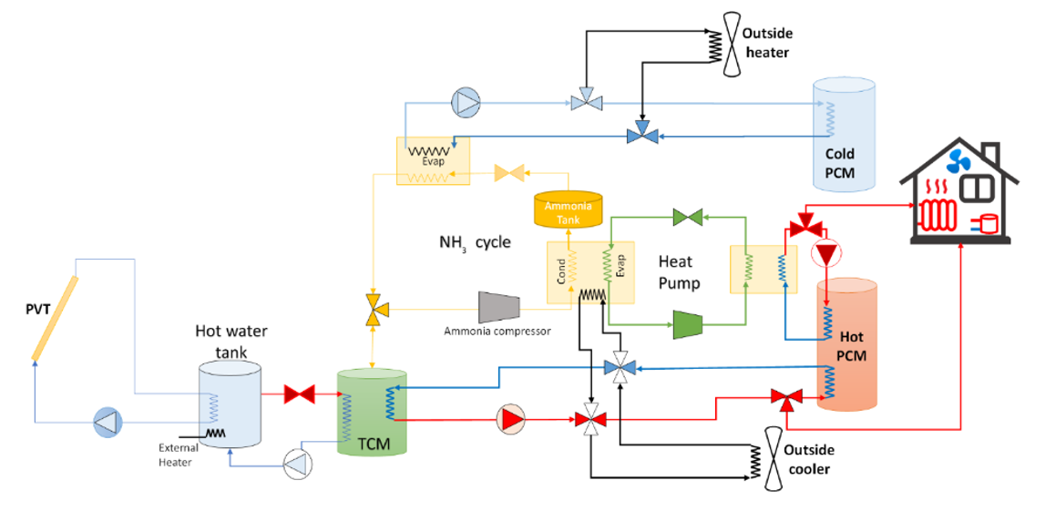
Figure 1. Overview of MiniStor thermal system components.
MiniStor was first installed at CERTH’s Smart Home in Thessaloniki, Greece (40.56°N, 22.99°E) for testing purposes before deployment at the four demonstration sites. The building has two floors and 317.7 m² of habitable area (182.7 m² on the ground floor and 135 m² on the first floor). Currently used as office space, the building operates mainly during business hours. The system serves a room of 49 m² (‘Control Room West’) via a fan coil unit (6 kW heating, 4 kW cooling) directly connected to the PCM tanks (Figure 2).
Piping between the solar field, container, and the Smart Home is insulated and buried to minimise heat losses.
In winter, heat is supplied in two modes:
Charging Mode: Heat for salt desorption is provided by the solar field, supplemented as needed by a 2kW electric backup heater. Heat input initiates endothermic decomposition reactions in the TCM reactor, generating NH₃ gas. The NH₃ gas is compressed, condensed, and stored. The heat released during condensation is upgraded to 336 K by a heat pump to meet building heating demands.
Discharging Mode: Used during nights or on cloudy days. Stored NH₃ evaporates when the ambient pressure corresponds to a temperature below the reactor’s equilibrium pressure. The resulting exothermic reaction releases heat at temperatures between 330 and336 K in the reactor. Excess heat is stored in the hot PCM tank.
During summer, part of the cooling load is met via NH₃ evaporation. The cold output is stored in a PCM tank with a melting temperature of 284 K.
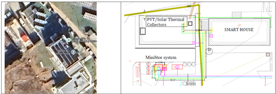
Figure 2. Location of the MiniStor in the Thessaloniki site.
All MiniStor components are housed in a 17.3 m³ container, which is equipped with comprehensive safety systems (Figure 2). The solar array consists of:
- 10 PVTs: Each has an aperture area of 1.55 m²; optical efficiency 0.51; heat loss coefficients α₁ = 4.93 W/m²K, α₂ = 0.021 W/m²K; and 260 W peak power.
- 5 FPCs: Each has a gross area of 2.37 m² gross area; optical efficiency 0.823; and heat loss coefficients α₁ = 3.36 W/m²K, α₂ = 0.013 W/m²K.
The collectors are installed at a 37° tilt – facing south (Figure 3). An external heat exchanger prevents system overheating. A water buffer tank and a 2 kW electric heater support consistent thermal input. An automation system manages thermal fluid recirculation based on solar output, ensuring the TCM is supplied with consistent heat. The TCM reactor, a key MiniStor innovation, is based on a reversible reaction between NH₃ and CaCl₂ (Equations 1 and 2).
 (1)
(1)
 (2)
(2)
The reactor contains seven 1.25 m-long tubes (114.3 mm diameter), forming two sub-reactors with a combined thermal capacity of 17.5 kWh. CaCl₂·4NH₃ offers superior heat storage performance compared to those in zeolites [16].
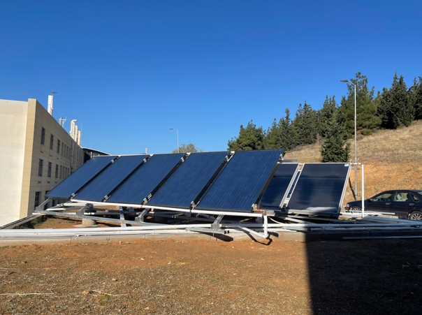
Figure 3. MiniStor’s solar array.
A custom R410A refrigerant heat pump boosts NH₃ condenser heat from 301K to 336K for delivery to the HVAC system or storage in the hot PCM tank. The refrigerant cycle involves compression to 4200kPa at 294K, condensation at 337K, and an expansion phase. The building’s cooling and heating demand is met by a fan coil that absorbs thermal energy from two dedicated PCM tanks. A hot PCM tank stores 3.5 kWh at 331 K (volume: 0.09 m³) and supplies the fan coil through pre-insulated polyurethane-aluminium (PPA) piping, while a cold PCM tank stores 6 kWh at 284 K (volume: 0.22 m³) and collects surplus cooling from NH₃ evaporation. MiniStor complies with EN 378, ensuring the NH₃ charge remains below 50 kg and housing all NH₃ equipment in a separate restricted compartment with emergency access, lighting, and alarms (Figure 4).
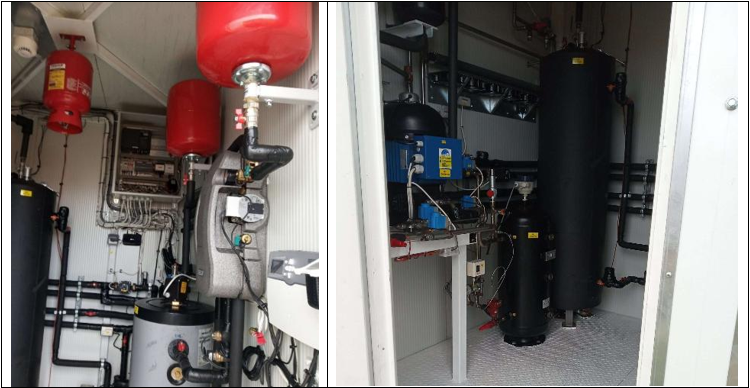
Figure 4. MiniStor NH3 container.
Initial simulation results indicated that the system could meet at least 69% of the total heating and cooling demand using energy produced locally by the PVT array.
To monitor the system, an IoT platform has been developed following a centrally focused approach, where all IoT components interact with it via a Representational State Transfer (REST) application Programming Interface (API). The platform’s user interface (UI) was implemented with Angular, while the back end was developed with Node.js.
The data monitoring process involves transmitting data from each demonstration site’s devices, after local aggregation on gateways, to the respective databases via a REST API (Figure 5). Then, the platform’s UI retrieves the data to generate interactive plots and to optimise the operation of the system. The API handles the data in JavaScript Object Notation (JSON), a standard, human-readable format for server communication. JSON consists of key-value pairs or key-value pairs or, for more complex structures, key-serialisable-value pairs.
Data acquired by using the MiniStor system are collected and handled in accordance with EU legislation and the national legislation of each demonstration site, including the General Data Protection Regulation (GDPR) for personal-data protection.
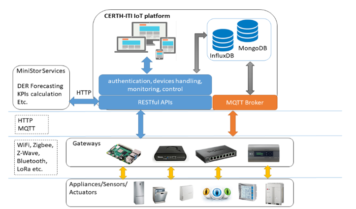
Figure 5. IoT MiniStor Platform.
Data security is ensured by following approaches compliant with the core principles of information security: availability, integrity, and confidentiality. Sensor data are collected securely over Hypertext Transfer Protocol Secure (HTTPS). In addition, the data collection in each demonstration site is monitored to ensure correct operation and data integrity. Multi-tenancy is supported; tenants have access only to their own data. These properties are achieved through the utilisation of a secure REST API, providing controlled access via encrypted user authentication and promoting data anonymity.
The REST API interfaces with two databases. One database (MongoDB) stores device, user, and site details. A second database (InfluxDB) stores device monitoring data. The structure of the databases supports the differences in the demonstration sites’ local requirements and configurations. Access to the data is available via the user interface of the IoT platform or direct querying. The data can be accessed directly through the databases, but this method is not available publicly, as it is not a good practice due to exposure to security risks. Such security risks could be data access by unauthorised personnel or deletion of data. Instead, communication is performed through specific endpoints of a REST API that require user authentication to enhance safety and privacy.
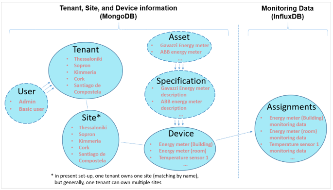
Figure 6. Main Endpoints of the IoT’s MiniStor Platform REST API.
The API offers multiple endpoints, but the main ones are the site, user, tenant, assignments (for monitoring data), device, specification, and asset (Figure 6). The site endpoint allows interaction with information about demonstration site locations. The user endpoint defines user types and their privileges (e.g. basic user or administrator), while the tenant endpoint manages one or more demonstration sites. The asset and specification endpoints are used for the metadata of the devices, while the device endpoint assigns a token serving as the device ID for the monitoring-data uploads via the assignments endpoint. Finally, the assignments endpoint supports uploading and retrieving monitoring data.
The UI displays a summary of system and environmental conditions, including both internal and external parameters. External data derive from a weather station. On this tab, users can monitor the dwelling’s overall energy consumption. They can also find information about the battery status, stored charge level, and whether it is charging or discharging to meet building loads. Finally, they can view the proportion of dwelling energy needs met by MiniStor and the daily grid exports and imports.
The Data Analytics tab displays the solar array’s electrical and thermal production and consumption, as well as associated system costs, as graphs. Users can view battery status, including generation, load, and state of charge. The ‘Data Analytics’ tab allows users to choose ‘Real Time’ or ‘Historical Data’.
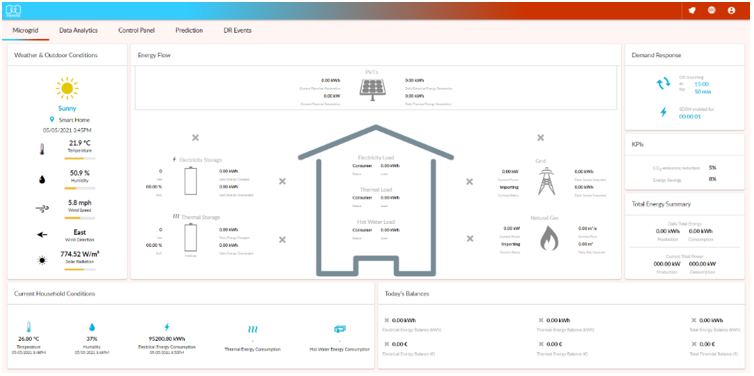
Figure 7. UI of the IoT MiniStor platform. Dashboard.
Figure 8 shows a test of charging the ammonia tank using both the solar fan coil and the solar array.
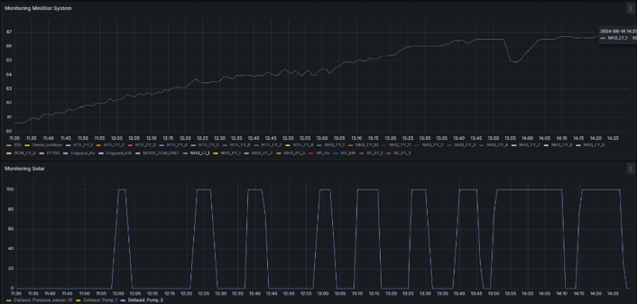
Figure 8. Ammonia charging during testing operation at the Thessaloniki pilot site.
Figure 9 presents validation tests of the ammonia-safety alarm thresholds. We conducted tests under real-life onsite conditions to fine-tune parameters—such as ammonia-tank pressure— that trigger the alarm.
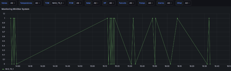
Figure 9. Ammonia Alarm threshold testing at the Thessaloniki pilot site.
Figure 10 shows that pressure testing determined the MiniStor system’s optimal operating pressure should be increased by 1 bar.
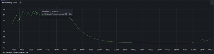
Figure 10. Pressure testing at the Thessaloniki pilot site.
Conclusions
The MiniStor system is a novel, compact, integrated TES system based on the reaction of CaCl₂ and NH₃ TCM material, combined with parallel hot- and cold-PCMs. Although compact, it exhibits an energy-storage density of 213 kWh/m3, offering a viable means to mitigate the intermittency of RES. Initial tests calculated the system’s annual performance and indicated that up to 69% of a typical building’s energy demands can be met by storing available solar energy in the TCM and PCM units under standard operating conditions. These findings underscore the MiniStor system’s strong potential for sustainable energy supply in buildings, especially when combined with intelligent control and optimisation techniques tailored to local climatic conditions.
References
[1] Bertoldi P., Diluiso F., Castellazzi L., Labanca N., Ribeiro Serrenho T., ‘Energy Consumption and Energy Efficiency Trends in the EU-28 2000-2015’, EUR 29104 EN, Publications Office of the European Union (Luxembourg), 2018.
[2] Martinopoulos, G., ‘Are rooftop photovoltaic systems a sustainable solution for Europe? A life cycle impact assessment and cost analysis’. Applied Energy, 257, 114035. 2020.
[3] Ecofys, Towards Nearly Zero-energy Buildings - Definition of Common Principles under the EPBD -Final Report, 2013.
[4] Duffie J.A., Beckman W.A., ‘Solar Engineering of Thermal Processes’, John Wiley & Sons (New York), 2013.
[5] Zisopoulos, G., Nesiadis, A., Atsonios, K., Nikolopoulos, N., Stitou, D., & Coca-Ortegón, A. ‘Conceptual design and dynamic simulation of an integrated solar-driven thermal system with thermochemical energy storage for heating and cooling’. Journal of Energy Storage, 41, 102870. 2021.
[6] Dinçer, İ., & Rosen, M. A. ‘Thermal Energy Storage: Systems and Applications’, Wiley. 2010
[7] Semadeni, M. ‘Storage of Energy, Overview’. In the Encyclopedia of Energy. 2004.
[8] Michel, B., Neveu, P., & Mazet, N. ‘Comparison of closed and open thermochemical processes, for long-term thermal energy storage applications’. Energy, 72. 2014.
[9] Mette, B., Kerskes, H., & Drück, H. ‘Concepts of long-term thermochemical energy storage for solar thermal applications - Selected examples’. Energy Procedia, 30. 2012.
[10] van der Pal, M., & Critoph, R. E. ‘Performance of CaCl2-reactor for application in ammonia-salt based thermal transformers’. Applied Thermal Engineering, 126, 518–524. 2017.
[11] Oliveira, R. G., Wang, R. Z., & Wang, C. ‘Evaluation of the cooling performance of a consolidated expanded graphite–calcium chloride reactive bed for chemisorption icemaker’. International Journal of Refrigeration, 30(1), 103–112. 2007.
[12] Wang, L. W., Wang, R. Z., Wu, J. Y., & Wang, K. ‘Compound adsorbent for adsorption ice maker on fishing boats’. International Journal of Refrigeration, 27(4), 401–408. 2004.
[13] Fitó, J., Coronas, A., Mauran, S., Mazet, N., Perier-Muzet, M., & Stitou, D. ‘Hybrid system combining mechanical compression and thermochemical storage of ammonia vapour for cold production’. Energy Conversion and Management, 180. 2019.
[14] Lahmidi, H., Mauran, S., & Goetz, V. ‘Definition, test and simulation of a thermochemical storage process adapted to solar thermal systems’. Solar Energy, 80(7). 2006.
[15] Zisopoulos et al., D3.1 ‘Initial dimensioning of the system according to general use typologies’, Project deliverable MiniStor. 2023.
[16] Fitó, J., Coronas, A., Mauran, S., Mazet, N., & Stitou, D. ‘Definition and performance simulations of a novel solar-driven hybrid absorption-thermochemical refrigeration system’. Energy Conversion and Management, 175. 2018.